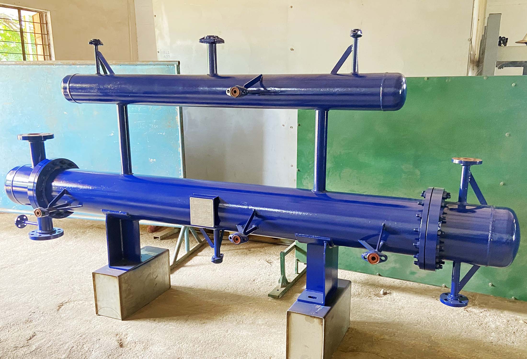
Shell-and-Tube Heat Exchangers
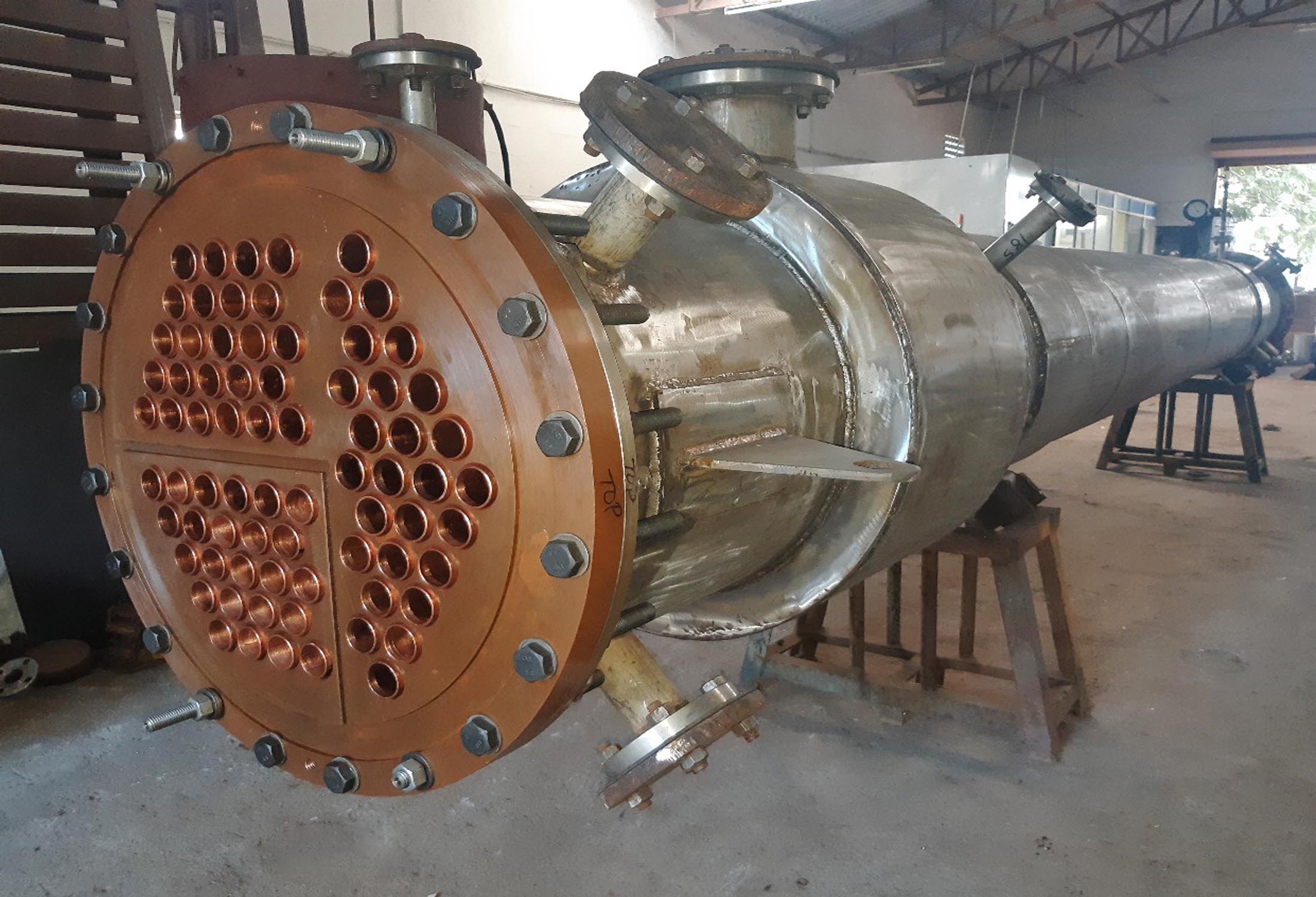
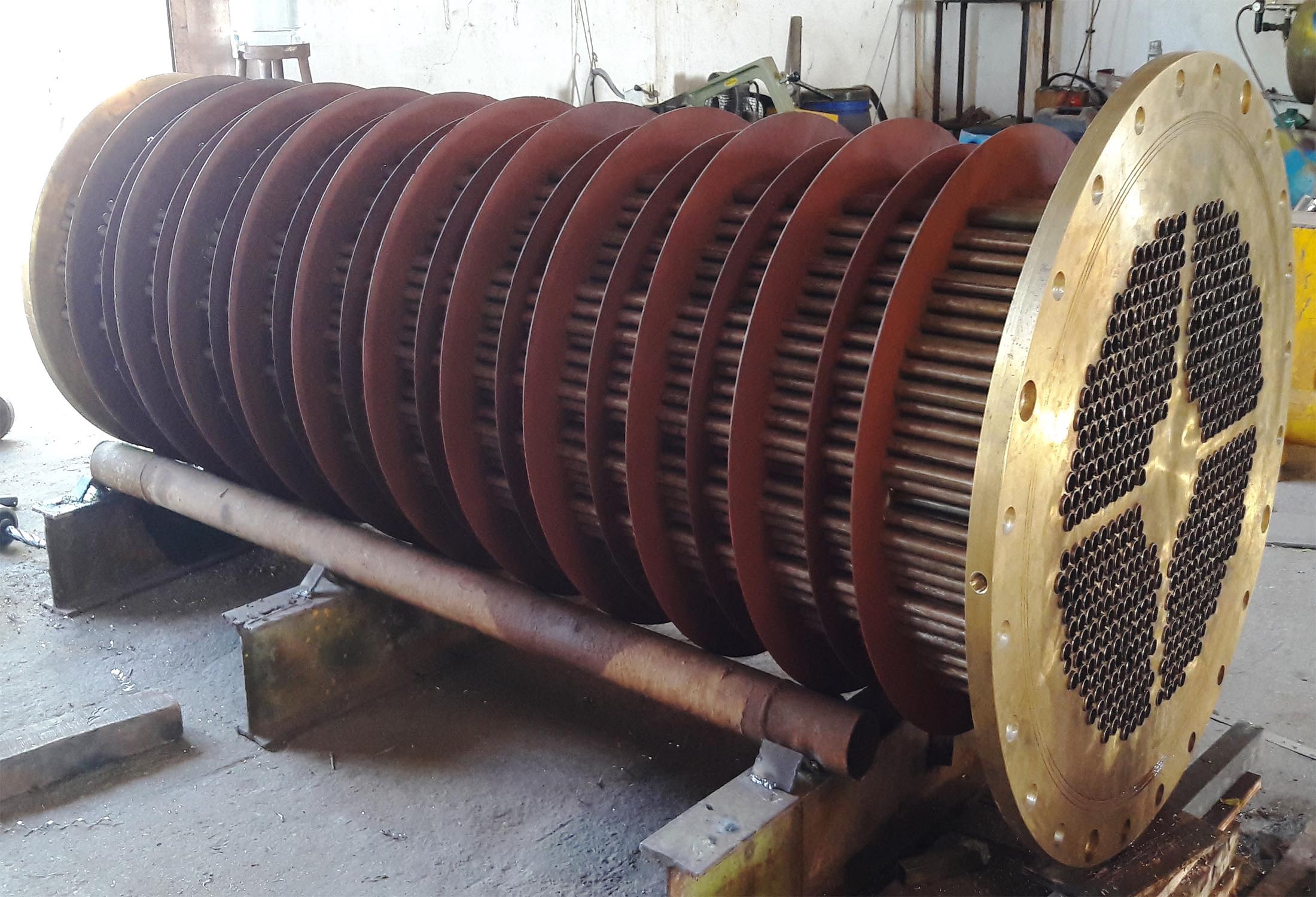
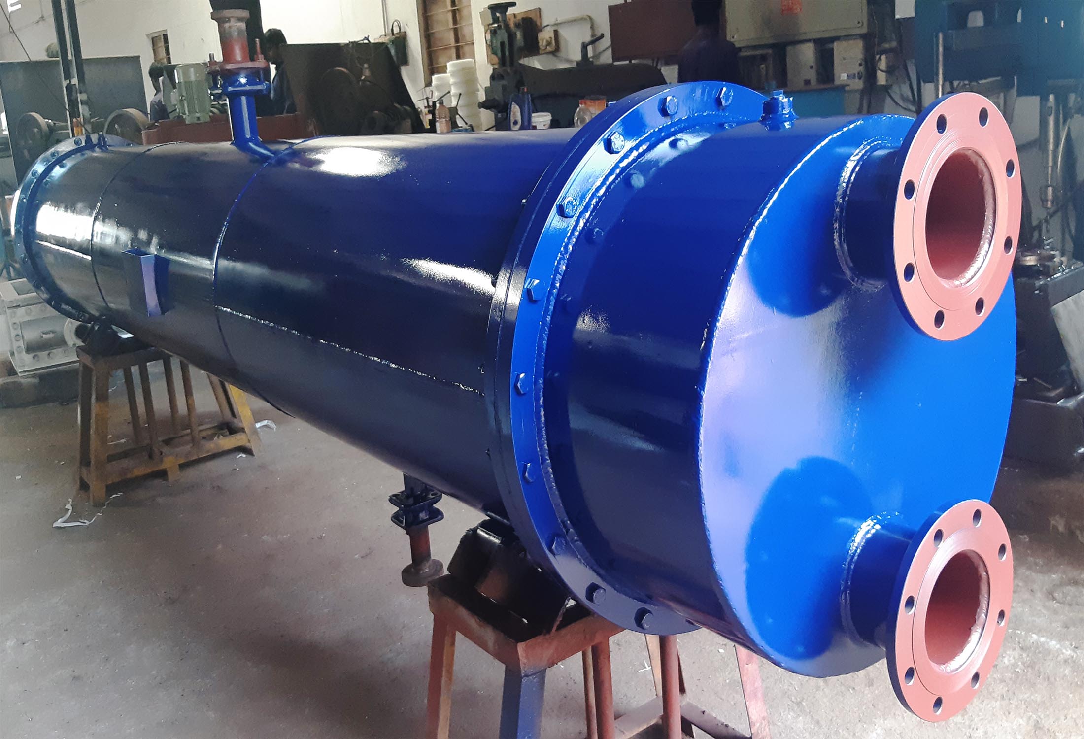
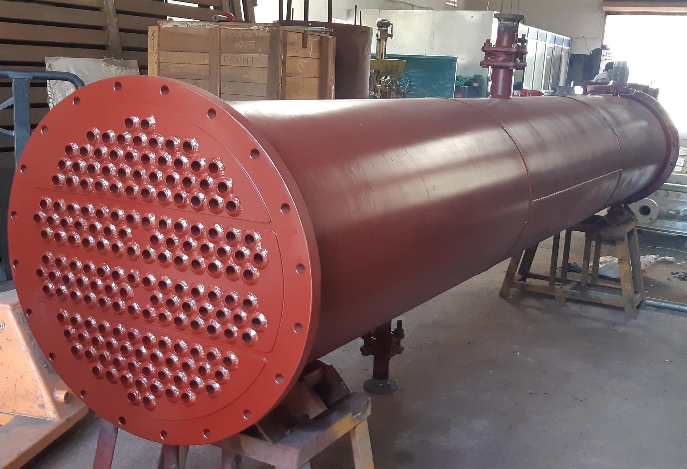
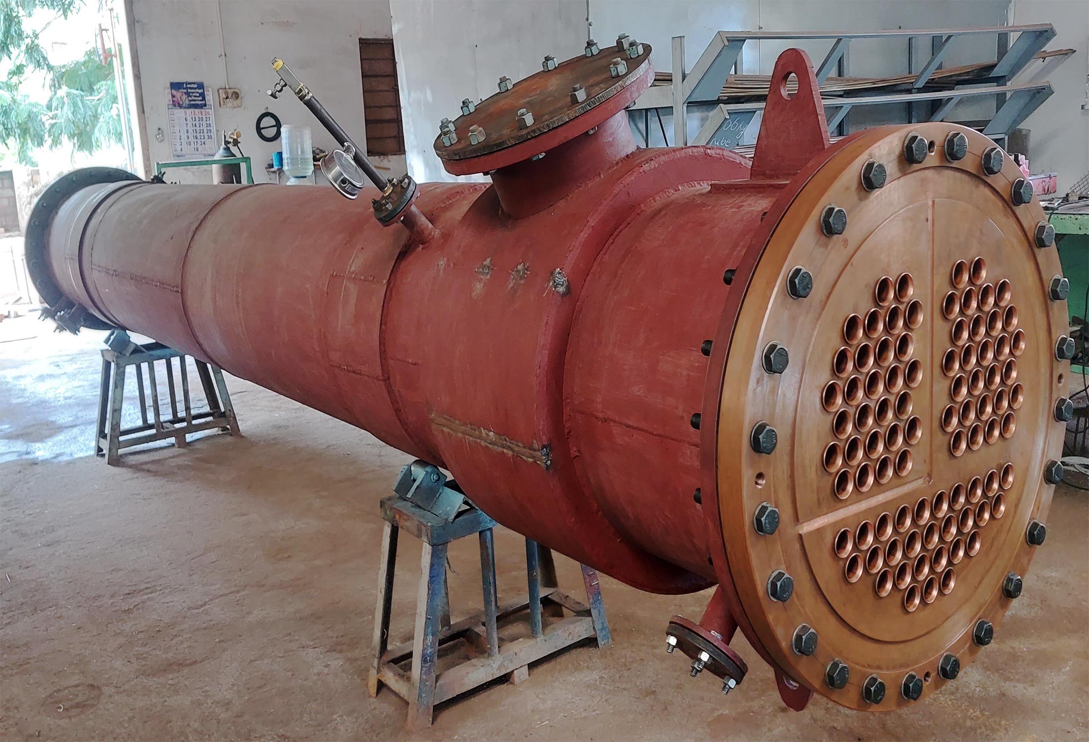
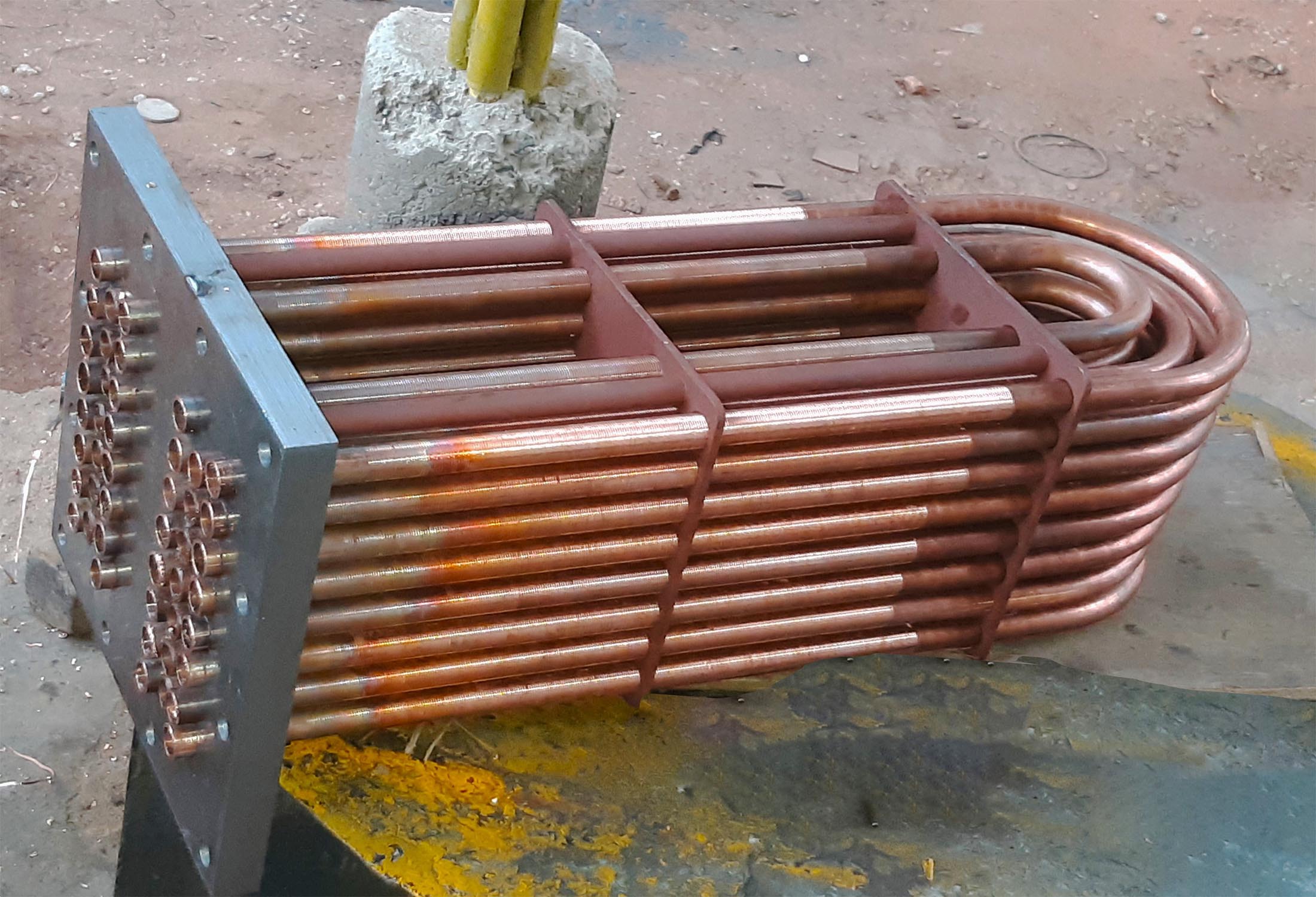
The shell-and-tube heat exchanger design allows heat transfer between two independent pressurized chambers through the wall of the tubes. The design consists of an array of tubes, which is connected on each side to a flat plate called a tube sheet. The tube sheet also separates the shell and tube sides of the exchanger. Baffles on the outside of the tubes direct the flow of the shell-side fluid back and forth across the tubes to promote heat transfer. The process fluid can flow through either the shell or tube side, with the opposite side typically acting as the service side (usually a heating or cooling medium). The exchanger also can have a process fluid on both sides.
For most shell-and-tube heat exchanger types, the first step in designing a heat exchanger for a specific process is thermal design. Given the process conditions and heat transfer requirements, the thermal design determines the exchanger’s size, shape, number and size of tubes, number of baffles and baffle pitch, etc. Other factors considered at this stage include allowable pressure drop through the exchanger, any space constraints on the unit, the potential fouling of the unit and any resulting flow-induced vibration from the proposed design.
Shell and Tube Heat exchangers are divided into 3 main categories:
1) Straight Tube Fixed Tubesheet
2) Straight Tube Floating Tubesheet
3) U-Tube Heat Exchanger
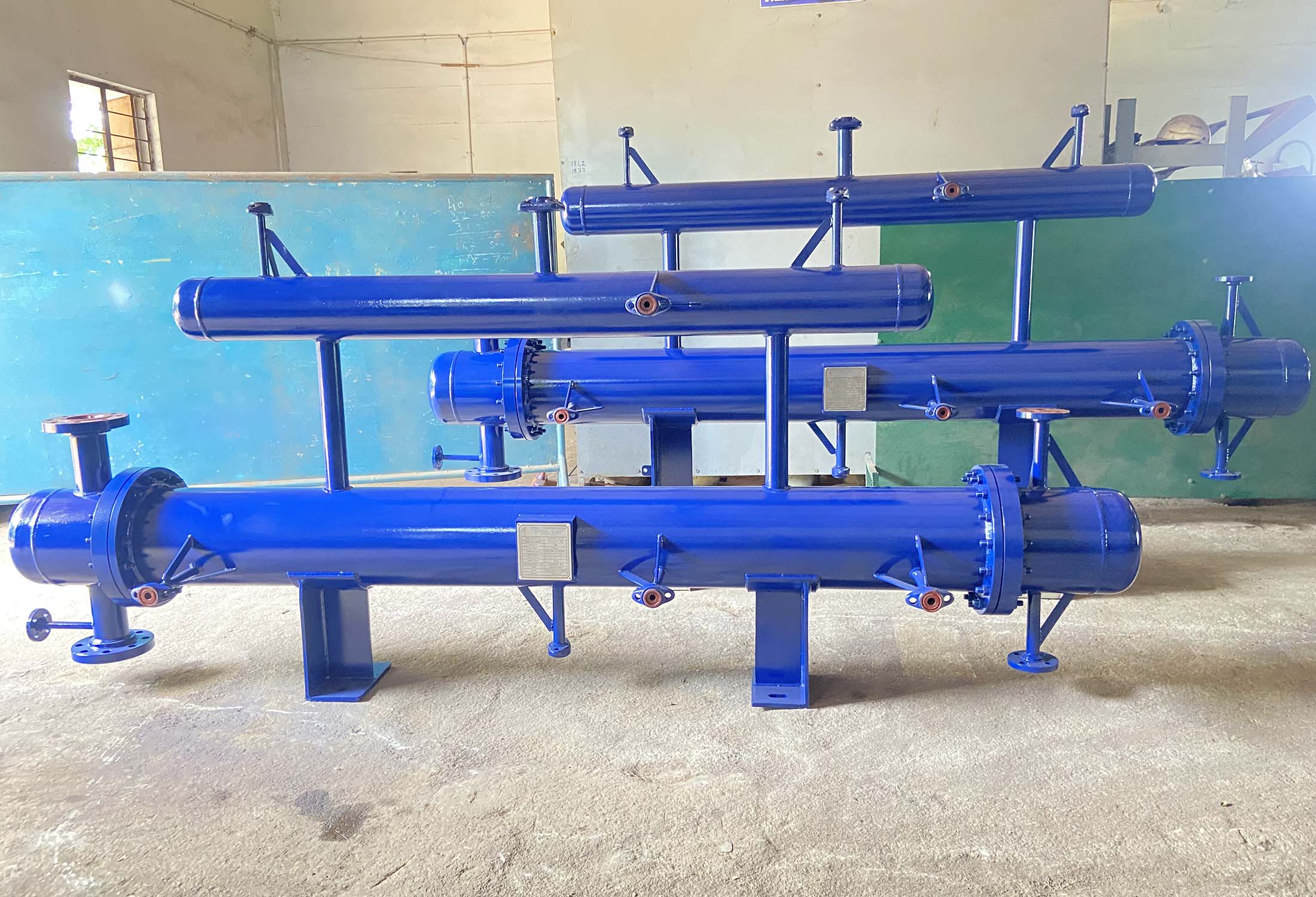
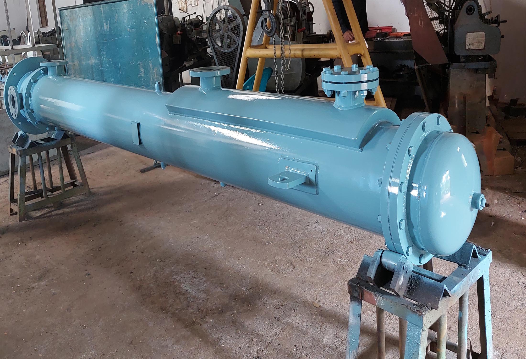
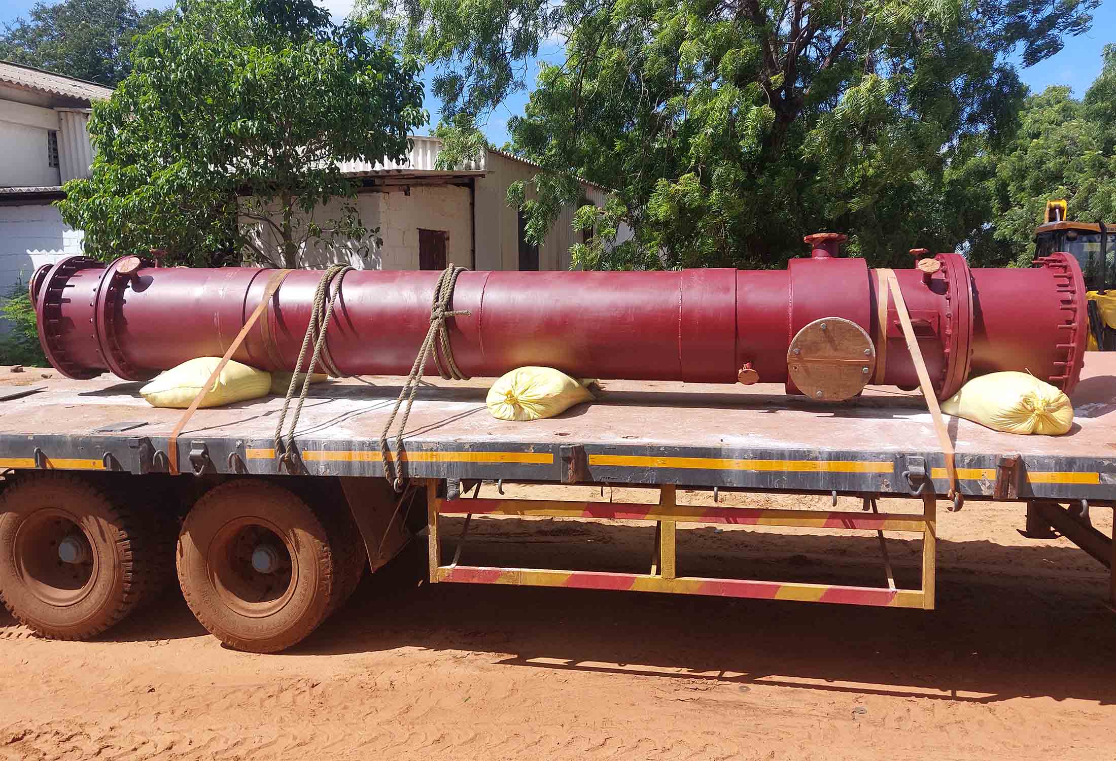
We, EEW excel in designing and fabricating all three types of shell and tube heat exchangers according to the client needs.


